Thanks @Svarky
I’ve updated the Charger firmware a few times.
It came with 1.14, and now at 1.16.
My iPhone App version is 8.14.1
I can’t see any of the options in your screenshot.
Makes me think Solargain have installed a non-Solar DLB. ![]()
Thanks @Svarky
I’ve updated the Charger firmware a few times.
It came with 1.14, and now at 1.16.
My iPhone App version is 8.14.1
I can’t see any of the options in your screenshot.
Makes me think Solargain have installed a non-Solar DLB. ![]()
Thanks heaps mate. That should do fine. I appreciate you replying.
@Ando, yes, that’s what the app looks like without the Solar DLB.
Can you see the DLB unit in your switchboard (or meterbox) or is it hidden behind the panel? If you can see it, it’s very obvious which one you have.
Thanks for confirming @Svarky.
That’s what I suggested to Solargain’s installation manager, who told me it was a Solar DLB box.
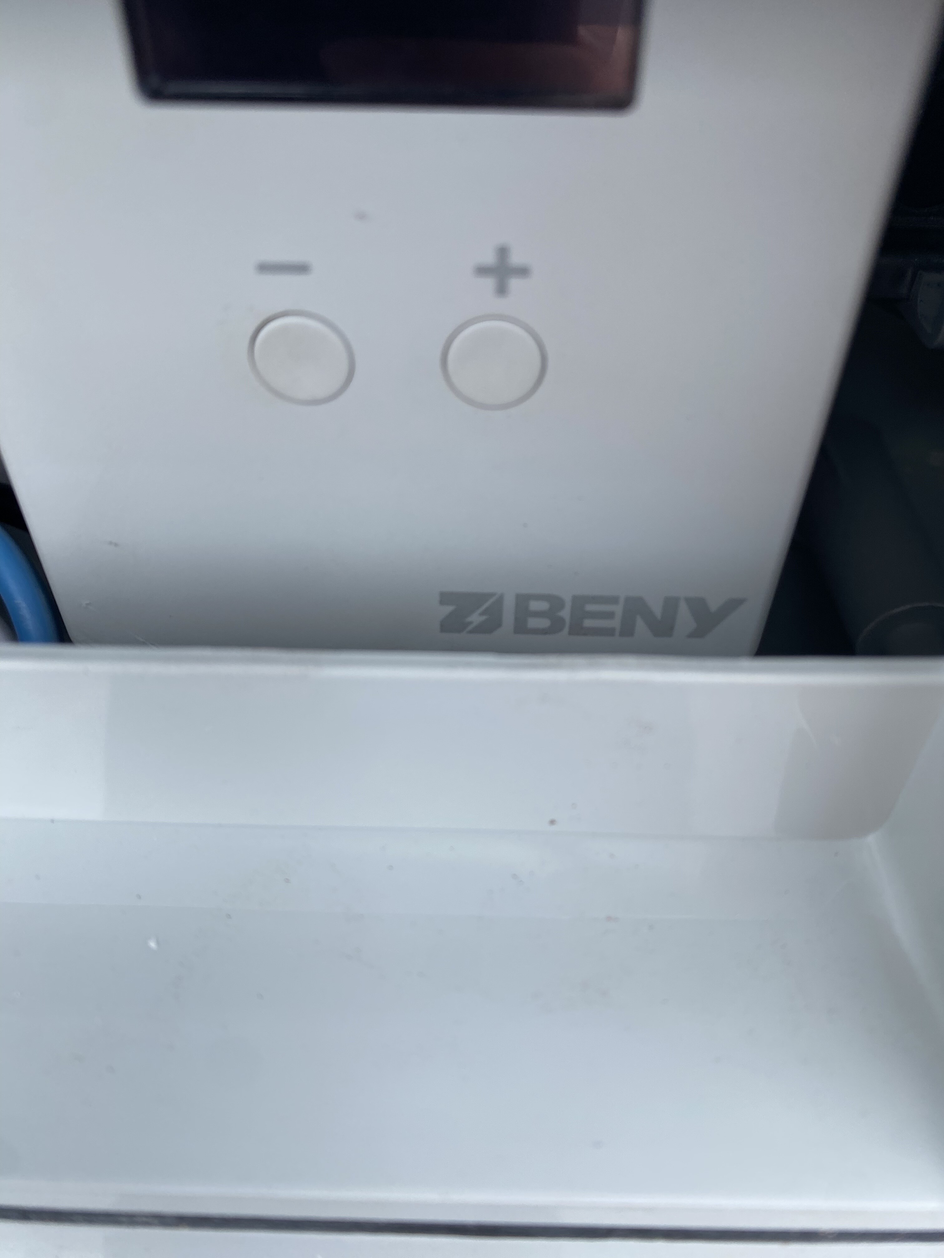
Here’s the a picture of the one they’ve installed.
No mention of solar on the box, which I believe is the differentiator…
That’s not the solar DLB, there’s your problem. Is it even on? What does the display look like when you press a button?
We recently installed a ZJ Beny three phase charger and took delivery of our electric vehicle (EV). Upon plugging in the charger to the EV, the charging process starts but then stops after about 30 seconds. The accompanying app displays an abnormal error icon and when pressed, shows a message “DLB Wiring Failure” (refer to attached image). We are currently arranging for the installer to investigate the issue, but would like to know if anyone else has experienced a similar problem in the past.
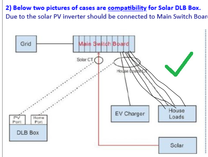
@Beevs, I had the exact same issue. Not sure if you read the earlier posts, but it was because the CT clamp was placed around the wrong cable. The Beny charger uses an unusual configuration which is not the same as most solar inverters and EV chargers. With the Beny Solar DLB unit, the grid clamp must go around all the loads, including the EV charger, not the incoming mains.
(I assume you have the optional solar DLB unit installed and not the regular load-balancing BLD unit that comes with the charger?)
Thanks you very much @Svarky . Yes I have the optional solar DLB unit installed not the regular load-balancing BLD unit. I will pass this onto the electrician tomorrow. Cheers
Thanks for you info to date. Much appreciated for those reading.
@Svarky
So I am clear in my mind (have read all the installation, and am having ongoing discussions with my electrician before installation) in a 1P 32A setup (with the Solar DLB), one CT goes around the solar feed, and the other CT goes around all loads (but not the mains feed).
Is that the crux of it?
@pedro yes, one CT goes around the solar feed cable, and the other goes on all loads, including the EV charger. The latest diagram from the new installation manual in quite clear.
The problem with this setup is that it can be extremely difficult to place a CT clamp around all the load cables and the EV charger cable. This is why most other EV chargers locate the CT around the main grid feed cable (1 cable) and solar cable, then measure the difference between the loads and solar.
The 3-phase version is the same, except across the 3 phases.
Thanks.
Makes sense, and hopefully it is doable in my fuse box layout. Initial inspection of it so far suggests it may be possible without changes (there is a spot that the load feeds are already close to each other, as long as we remember to route the new ZJBeny load feed via the same area also).
Rather than trying to fit (every household load + EVSE) circuits through one CT, wouldn’t it be easier to just put that CT around the (mains - solar)? That is, have the mains and solar running in opposite directions through that CT so that the difference in current is measured?
@PVEVHP, Yes, that would be far easier, but unfortunately, that’s not how ZJBeny designed the solar DLB box to work. If you look back through this discussion, I contacted them about this issue, and they are aware of the problem. They should be releasing a new solar DLB unit at some stage in the future.
Hi @Svarky thank you for the guidance you provided above. The electrician made the necessary adjustments to the DLB installation and tested the charger this morning. All was working fine, however I have just plugged the charger into the EV again and am being presented with the same DLB Wiring Failure Error message. Do you have any other suggestions as to what the issue may be.
TLDR; Anyone know why my charger would be tripping, or not using the full solar excess?
Ok. I’m feeling like a Guinea Pig with this charger.
The installers have returned and installed the correct Solar DLB unit.
I now have the PV and Hybrid options on my Z-Box App.
And now onto the next set of issues.
issue #1. The box keeps tripping, no matter which charging option I choose.
Issue # 2. On PV mode, and before tripping, the max I could get the charger to charge at was 8a - 5.7kw.
At that time I was generating 10kw, and using 1kw.
The only time I could get an extended charge, seemed to be when I closed the App. I got maybe a half-hour charge doing this, before it tripped. Doh.
I’ll try another trouble-shooting session this weekend.
@Ando, by tripping, I assume you mean the safety switch (RCD circuit breaker) is tripping in your switchboard? This shouldn’t be happening. There might be an issue with your wiring or connections. What size breaker is it? (How many amps?)
Try charging at a lower rate, say 4kW, for a few hours and see if it trips. If it doesn’t trip, then you probably have a high resistance (thermal) issue somewhere in the setup.
5.7kW is more like 24A, not 8A.
Sorry 8a showing on the Tesla App.
This equates to 5.7kw on a 3phase system.
8 x 240 x 3 = 5,760watts.
Thanks @Svarky.
It’s the Box which keeps faulting. Stops charging and starts flashing orange.
Will try your lower charge rate suggestion over the weekend.
For the charge rate topping out at 5.7kw on PV only mode, I’m thinking it could possibly be because I have 2 x 5kw inverters, but the installer didn’t think this would be the reason. I hope they’re right. Hmmm.
Thanks for the reply, and for generously sharing your wisdom here.
I have been following the entire thread since the beginning, I fear I haven’t explained myself correctly.
If I understand the issue, the reason that the presently available DLB doesn’t work, is that this isn’t possible with the standard Australian wiring:

The reason being that most houses have a bunch of load circuits, and it would be mechanically impossible to get them all through the Load CT (sorry/not sorry for the MS Paint wiring diagram):
I’ve done analog subtraction of currents by passing wires in opposite directions through a CT, so I was wondering if it would be possible to use that trick like so:
That is, rather than directly measuring the sum of all loads (house circuits + EVSE) just measure the difference (Grid - Solar), still requires getting two wires through a CT but might be possible.
?