Here are the results from my BYD Atto 3 vehicle-to-load (V2L) testing. There was some conflicting information online about the power output rating from the Atto 3 being either 10A or 15A so I decided to find out for myself. I was assuming the power output would be closer to 10A continuous with a 15A peak output rating and it appears this is the case.
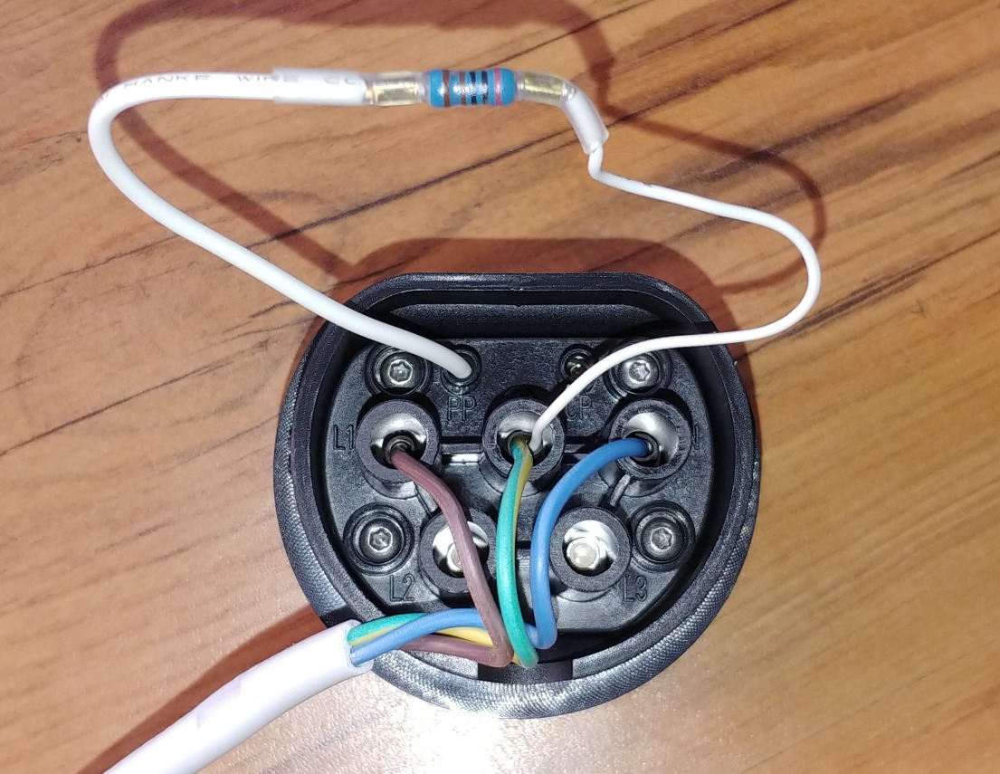
My Test Setup: I have an off-grid solar-powered house running on a Victon Multiplus 2 inverter-charger (plus VRM and CCGX display) with a 15A input power socket which can be used for a backup generator or any other AC power source. The BYD Atto 3 comes with a V2L adapter with a 4 port power board as standard. This is a little strange as it is not weather rated, and I would prefer to have a single socket and plug in a power board if needed. So before I could conduct the testing I pulled apart the type 2 connector apart and replaced the cable with a larger 1.5mm2 (15A) cable and plug.
Ok, so the initial test with no loads showed using my showed a V2L voltage of 218V and a frequency of 50.1Hz. Since I’m in Australia, I’m used to 240V, but 220V AC is standard across much of Europe, SE Asia and China.
TEST 1 - First load test was 10A which dropped the voltage to around 210V and the frequency was stable. It powered this load no problem for 15 around minutes and the frequency was stable.
TEST 2 - I ramped up the load to 12A which the vehicle was able to supply but the frequency started to fluctuate slightly. The voltage was fine at 210V
TEST 3 - I increased the load to 15A but it appeared to be unable to supply much more than 14A for more than a few seconds. The frequency fluctuations appeared to prevent the Multiplus inverter from continuously drawing more than 12A.
RESULTS: It appears the V2L continuous load rating is 10A at 220V (2200W) with a peak (short duration) output of around 15A. However, in a preliminary load test, I was also able to run an 2200W electric kettle and a 1000W toaster for a few minutes so this indicates it can supply around 3200W to simple resistive loads for a longer duration.
@bentienergy no, unfortunately, Tesla does not yet have this function. Although it is rumoured that the hardware is capable, but Tesla has not yet enabled it. It’s strange as it would be another great selling point
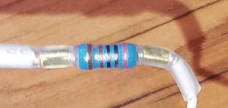
Hi. Thanks for the testing specs. Can you please measure the resistor value between PP & PE(earth)?
Is there no ON/OFF switch on the type-2 plug? Or indicator light? Do you have a copy of the circuit inside the plug? Thank you.
Hello and thanks for the great pictures. Did you measure the resistor? It looks like 110 Ohms with a pink tolerance band. Maybe.
It is a little odd as on the Hyundai IONIQ 5 and KIA EV6 V2L units, as well as a resistor between PP & PE, there is a switch across PP & CP which needs to be closed to activate the 230VAC output.
Thank you for the diagram. That’s a bit odd as the resistor in Svarky’s picture is not 2700, the colours read 2000. I initially thought 110 but on a second look I think that it is 2000, 1%.
Do some versions of BYD vehicles in NZ come with a V2L lead?
Yes, We’ve just started getting the VTL adaptors. Being couriered out to owners. Comes with a 2 way multibox, on which is an on off switch and a reset button. It has max power of 2400W and pokes out approx 216V AC. Oh, and there is a power on, power off led.
The colours in the photo are misleading.
The value is 2k7 Ohms, 1%. The red looks pink on my screen, the violet is almost indistinguishable from the black.
Red, Violet, Black, Brown, Gap, Brown.
Anyhow, can’t someone stick an Ohmmeter on one to check? PP to PE.
It’s possible that resistance doesn’t actually mean much in the context of an Atto 3. The voltage is fixed, and so is the maximum current, and maybe open CP-PE plus some range of resistance on PP-PE is all that’s required. (But then why the 1% component?)
Question all.
Would you expect the Atto3 VTL would provide power to a house via a generator socket on a house where the house has been isolated from the grid using a manual transfer switch?
Either using a 3 pin to 32 amp lead via the new 2 way multibox on the BYD supplied VTL adaptor, and/or
Using a setup as above and using the ccs2 plug and appropriate cable to a 32 amp adaptor.
Is there anything in the solar inverter referenced above that makes the car more likely to connect directly to it, as opposed to a generator inlet?
Also, is the single resistor and location the thing that tells the car to discharge? I.e. i assume one couldnt repurpose a charging lead as a vtl adaptor for #2 above?
After the cyclone hammering us here in NZ, and folks being without power for a week and likely another week or two, its got me thinking about options.
@DazzaG, If you are powering house circuits directly from the vehicle (not using an off-grid inverter), then you just need an input socket (15A or 32A), and a double-pole manual AC transfer switch. The double-pole switch is needed to isolate the neutral and active supplies from the grid since the V2L operates as an independent (floating) supply, much like a portable generator. Ensure the RCD safety circuits are all operational by a certified electrical professional.
Edit: For safety reasons, an EV with V2L provides a ‘protected’ AC supply. If powering protected circuits (RCDs) then this can interfere and trip the V2L supply. If this occurs a separated (isolated) V2L circuit may need to be installed.
If you have a grid-connected solar system, it must be isolated and cannot be connected to the V2L circuits. An off-grid inverter-charger is very different; most can be configured to operate with a floating (portable) generator. Lots more information about using V2L for backup power here.